3.1.1. PWM
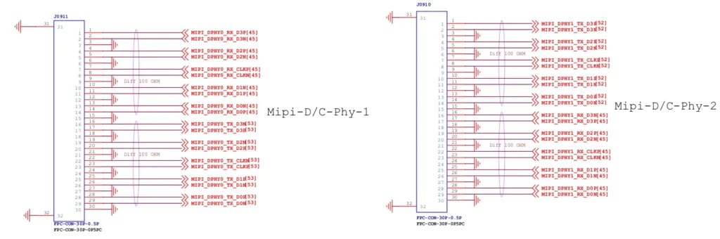
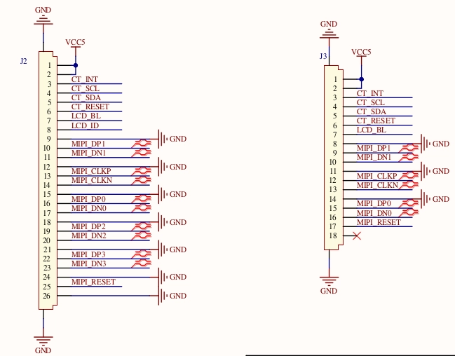
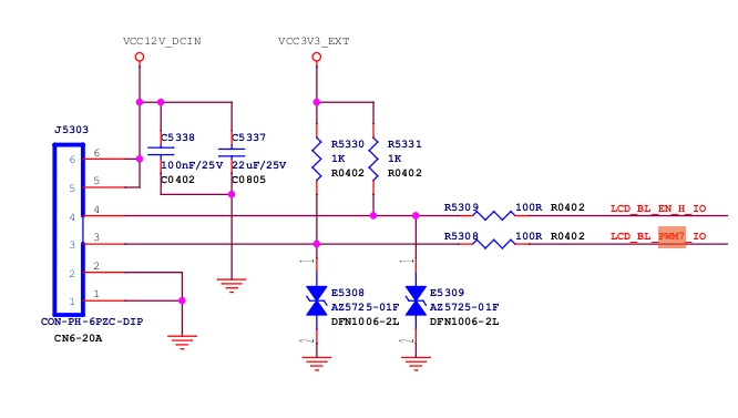
The screen backlight is controlled by PWM, and the screen brightness is adjusted by the PWM waveform. In the interface diagram, Pin7 (LCD_BL) is used to control the backlight. Since the MIPI interface is not brought out on the LKD3588, there is naturally no related pin configuration. Since the PWM7 pin of the LKD3588 is brought out, we directly use PWM7 (PWM7_M3_GPIO4_C6_d_IO3_1V8) to control the backlight, and connect GPIO4_C6 to the LCD_BL pin of the MIPI screen.
GPIO4_C6 pinctrl configuration, find the following in rk3588s-pinctrl.dtsi or rk3588-vccio3-pinctrl.dtsi:
1.pwm7 {
2./omit-if-no-ref/
3.pwm7m3_pins: pwm7m3-pins {
4.rockchip,pins =
5./* pwm7_ir_m3 */
6.<4 RK_PC6 11 &pcfg_pull_none>;
7.};
8.};
Then append the following to pwm7 in rk3588-neardi-android-ld160-mipi2hdmi.dtsi:
1.pwm7: pwm@febd0030 {
2.compatible = “rockchip,rk3588-pwm”, “rockchip,rk3328-pwm”;
3.reg = <0x0 0xfebd0030 0x0 0x10>;
4.#pwm-cells = <3>;
5.pinctrl-names = “active”;
6.pinctrl-0 = <&pwm7m3_pins>; // Use the configuration in rk3588-vccio3-pinctrl.dtsi
7.clocks = <&cru CLK_PWM1>, <&cru PCLK_PWM1>;
8.clock-names = “pwm”, “pclk”;
9.status = “okay”; // Enabled status
10.};
3.1.2. Backlight node settings
Because we only modify one interface, all modifications are added to the last level of the device tree file (rk3588-neardi-android-ld160-mipi2hdmi.dtsi), and the DSI device node is modified as follows:
39 00 04 B9 FF 83 94
39 00 07 BA 63 03 68 6B B2 C0
//15 00 02 36 01(Reverse display)
//15 00 02 36 02(Positive display)
15 00 02 36 01
39 00 0B B1 48 12 72 09 32 54 71 71 57 47
39 00 07 B2 00 80 64 0C 0D 2F
39 00 16 B4 73 74 73 74 73 74 01 0C 86 75 00 3F 73 74 73 74 73 74 01 0C 86
39 00 03 B6 6E 6E
39 00 22 D3 00 00 07 07 40 07 0C 00 08 10 08 00 08 54 15 0A 05 0A 02 15 06 05 06 47 44 0A 0A 4B 10 07 07 0C 40
39 00 2D D5 1C 1C 1D 1D 00 01 02 03 04 05 06 07 08 09 0A 0B 24 25 18 18 26 27 18 18 18 18 18 18 18 18 18 18 18 18 18 18 18 18 20 21 18 18 18 18
39 00 2D D6 1C 1C 1D 1D 07 06 05 04 03 02 01 00 0B 0A 09 08 21 20 18 18 27 26 18 18 18 18 18 18 18 18 18 18 18 18 18 18 18 18 25 24 18 18 18 18
39 00 3B E0 00 0A 15 1B 1E 21 24 22 47 56 65 66 6E 82 88 8B 9A 9D 98 A8 B9 5D 5C 61 66 6A 6F 7F 7F 00 0A 15 1B 1E 21 24 22 47 56 65 65 6E 81 87 8B 98 9D 99 A8 BA 5D 5D 62 67 6B 72 7F 7F
39 00 03 C0 1F 31
15 00 02 CC 03
15 00 02 D4 02
15 00 02 BD 02
39 00 0D D8 FF FF FF FF FF FF FF FF FF FF FF FF
15 00 02 BD 00
15 00 02 BD 01
15 00 02 B1 00
15 00 02 BD 00
39 00 08 BF 40 81 50 00 1A FC 01
15 00 02 C6 ED
05 64 01 11
05 78 01 29
];
I2C interface pins I2C1_SCL_TP and I2C1_SDA_TP, touch IC reset pin TP_RST_L and touch IC interrupt pin TP_INT_L

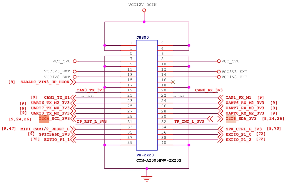
1.2. 3588-side hardware interface:
Use I2C6, interrupt pin uses GPIO3_PC0, reset pin uses GPIO1_PA4
Use I2C6, interrupt pin uses GPIO3_PC0, reset pin uses GPIO1_PA4
Add i2c device and match gt9147 related configuration in rk3588-neardi-android-ld160-mipi2hdmi.dtsi.
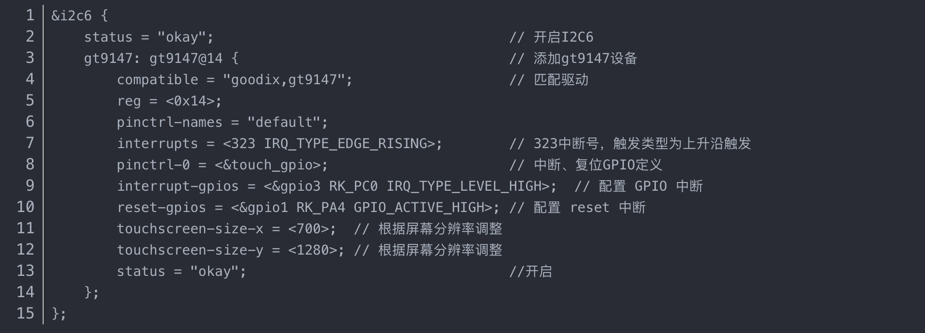
Interrupt, reset GPIO configuration
Add i2c device and match gt9147 related configuration in rk3588-neardi-android-ld160-mipi2hdmi.dtsi.
Interrupt, reset GPIO configuration