Building a custom Raspberry Pi-based laptop is an exciting project for tech enthusiasts and makers alike. The Raspberry Pi, known for its compact size (about the size of a credit card), powerful 1GB RAM, and 900MHz CPU, has been a favorite among creators for years. This tiny yet powerful device is capable of bringing ideas to life that were once considered impossible. In this guide, we will walk you through creating a super cool, mini laptop using a Raspberry Pi, inspired by the work of a creator named SilverJimmy. The key difference? We’ll keep it compact and efficient while ensuring everything fits together seamlessly.
Materials Needed for the Build:
Before you dive into your Raspberry Pi laptop project, make sure you have the following parts ready:
1.A 6”x6”x2 5/8” cosmetic case
2.Raspberry Pi B2 computer
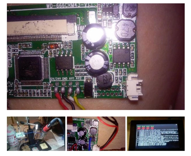
3.4.3-inch LCD display (12V)
4.RCA jack (female)
5.3.5mm audio port
6.3.5mm A/V cable
7.USB female port
8.Button switch (from an old computer)
9.SPDT switch (from an audio amplifier)
10.Cooling fan (optional)
11.3 blue LED lights
12.3 smartphone lithium batteries
13.USB charger
14.3V to 5V 500mA boost converter (from an old AA battery charger)
15.Superglue, jumper wires, and some electrical tape
16.Scrap wood (for construction)
17.Old DVD case (wooden or paper)
18.Computer screws
Tools Required:
1.Tape measure
2.Marker pen
3.Utility knife
4.Soldering iron and solder
5.Phillips screwdriver
Step-by-Step Guide:
Step 1: Adjust the LCD Voltage to 5V
This is a crucial step in your build. The 4.3-inch LCD screen I’m using operates on 12V, but for this project, we’ll reduce that to 5V so that the Raspberry Pi and the display can share a single power source.
Here’s how to modify the LCD’s voltage:
1.Open up the LCD and locate the 12V-to-5V converter (black, 8-pin, triangular-shaped).
2.Search online for the specifics of your converter input, then find the output interface and solder the 5V wire to it.
3.Power on to test. If done correctly, your LCD will now run on 5V, perfectly matching the Raspberry Pi’s power requirements.
Step 2: Install the Raspberry Pi
Before assembling your laptop’s outer shell, measure the space accurately to avoid issues during installation.
1.Mark the location where you want the Raspberry Pi to sit inside the case using a marker.
2.Drill a hole in the side for the USB and Ethernet ports.
3.Install the Raspberry Pi in the marked position and secure it with screws. To avoid short-circuiting, wrap some electrical tape around the USB and Ethernet ports because the case is metal.
Step 3: Mount the LCD
I initially considered adding a cushion for the LCD before mounting it, but later realized it wasn’t necessary. You can go ahead and secure the LCD directly in place.
I used some scrap wood to create a base, nailed it together, and attached the LCD to the base with screws. Then, I mounted the whole setup inside the laptop shell.
Ensure there’s enough space in the shell for both the LCD and the necessary wires to connect the Raspberry Pi.
Step 4: Install the Switches, Buttons, LEDs, Cables, and Connectors
A/V Connection:
The Raspberry Pi has both HDMI and composite A/V output. Since the LCD uses composite input, the HDMI port will not be needed. I bought a 3.5mm A/V cable, but it was too long, so I trimmed it down to fit.
The wiring on the Raspberry Pi’s 3.5mm jack is a bit different. Yellow is video, and red and white are for left and right audio channels, respectively. For video output, I used a single RCA jack, which handles both input and output. This allows the Raspberry Pi to display video content on an external device.
Button and Switch:
I originally thought I could manage with just one switch to control the laptop’s power. However, I realized I needed a separate button for the screen. The main power switch uses an SPDT switch, while the screen has its own button switch.
LED Indicator:
For the charging status, I used a blue LED connected to the Raspberry Pi’s 3.3V GPIO pin. This LED will indicate the power status of the system.
Step 5: Powering the Raspberry Pi and LCD
Power for the Raspberry Pi:
The Raspberry Pi doesn’t have great battery life—around three hours with regular use. I’m using a 3.7V, 2150mAh lithium battery to power the Pi, and it’s connected to a 5V universal power input/output port.
Power for the LCD:
Initially, I used the Raspberry Pi’s 5V port for the LCD, but the display started freezing after some time. To fix this, I decided to give the LCD its own independent power supply using two 3.7V 500mAh batteries connected in parallel, feeding into a 3V-to-5V boost converter. This way, the LCD operates smoothly without lag.
Charging the Batteries:
For charging, I used an old USB charger. The interesting part is that both the Pi and the LCD require different charging systems due to their varying power demands, so I set up individual charging circuits for each.
Step 6: Cooling Fan (Optional)
Running complex tasks causes the Raspberry Pi to heat up. To prevent overheating, many users install heat sinks or cooling fans. Since I didn’t have a heat sink, I found a small fan that fit perfectly over the USB ports and attached it. I powered the fan using a 5V universal port, ensuring the Pi’s temperature stays around 12°C under load.
Step 7: Final Assembly and Case Construction
The final step involves building the outer case for the project. I considered using cut cardboard initially but opted for an old DVD case. After measuring and cutting holes for the screen, control panel, and fan, I finished the assembly.
Though the case still looks a bit rough, it’s functional and practical. I also left space for a camera module, though I currently don’t have one installed.